![]()
| Twin Battery - Split Charge Install *Update - 02/12/2009* 05/11/2009 | ||||
|
|
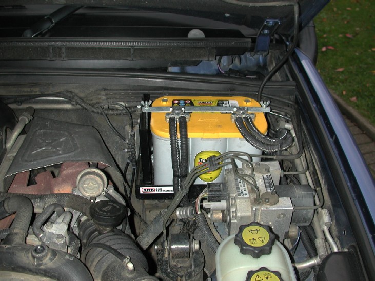
There is several reasons people install a twin battery, the most common is to power auxiliary circuits when the engine is not running like fridges etc when camping to keep the starter battery fully charged, to power an electric winch is also another reason as well as the aux circuits. Most cars and in particular 4x4's have some space under the bonnet where a second battery can be installed, the Discovery TD5 is no different. The "ideal" space is by the bulkhead on the passenger side of the engine bay, and unless your vehicle is fitted with a Webasto pre heater from the factory, this is the place to put an aux battery.
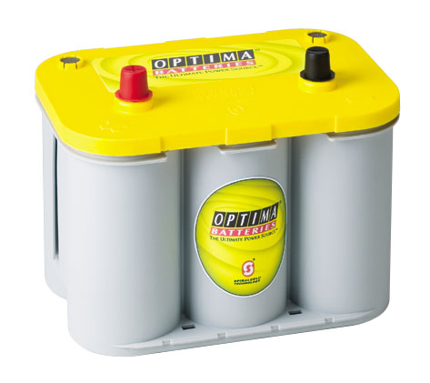
You can off course put one inside the car if you wish, but for me keeping it all under the bonnet makes sense and saves running to many heavy duty cables into the car. It is generally a good idea to use what's known as a "deep cycle" or leisure battery as your second battery, these batteries are designed to runs loads whilst the engine is not running, like when your camping and the fridge and maybe lights etc are running whilst the engine is not. Having the second battery means it can be run flat and the starter battery will remain fully charged for you to start the vehicle when needs be. Deep cycle batteries are constructed with thicker plates than standard vehicle starting batteries and are less likely to be damaged when being fully discharged. Which battery you chose is down to you, and there's is LOTS of info out there from different sources like forums, message boards and manufacturers etc, for me the choice was to go with an Optima Yellow Top which is dual purpose battery, which means it has deep cycling ability and can also pack a punch of high CCA's to start a vehicle if needs be.
Some say its best to have the 2 batteries the same when doing a twin install, whether that's true or not who knows, but as I already had a Yellow top as my main battery, it was an easy decision to get another as an aux battery. The space where your going to fit the second battery is the most important thing you need to consider when designing your system, The space by the bulkhead in the Disco 2 is a good space to fit a battery of BCI 34 spec / size, which is about what the Optima is. Once I had bought the battery, then the mounting is the next thing to consider, now I have seen several "home made" trays that have been installed in that space and they all work well, but I decided to see if there was a ready made tray out there to buy, well as usual the Aussies get all the goodies and there is 2 companies in Aus that make a tray for the Disco 2, ARB who we know make some excellent offroad equipment and Piranha also do one to. After seeing the ARB tray installed in few Auslro members vehicles I decide that was for me, so with the help of Neil on the Aus forum (thanks m8!!), one was purchased and shipped over to me. If I'm honest with the shipping costs etc involved, it was / is more expensive than "knocking" your own one up, but the tray is very well designed, fits beautifully in the space and mounts to existing vehicle mounting points.
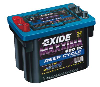
Now the tray is specifically designed with the Exide Maxxima battery in mind and the end plate is even designed as the "clamp" to hold the battery in place.
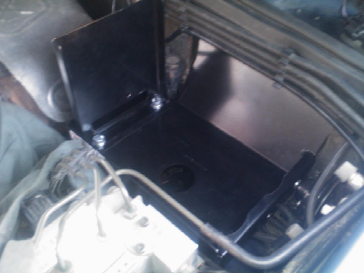
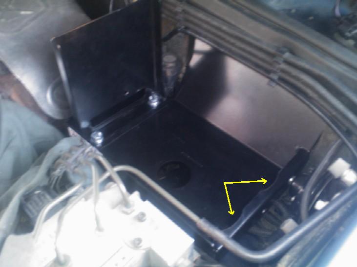
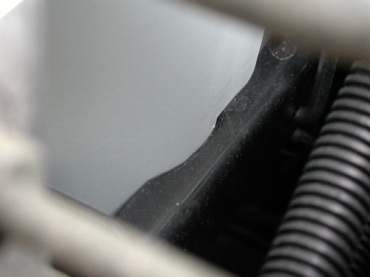
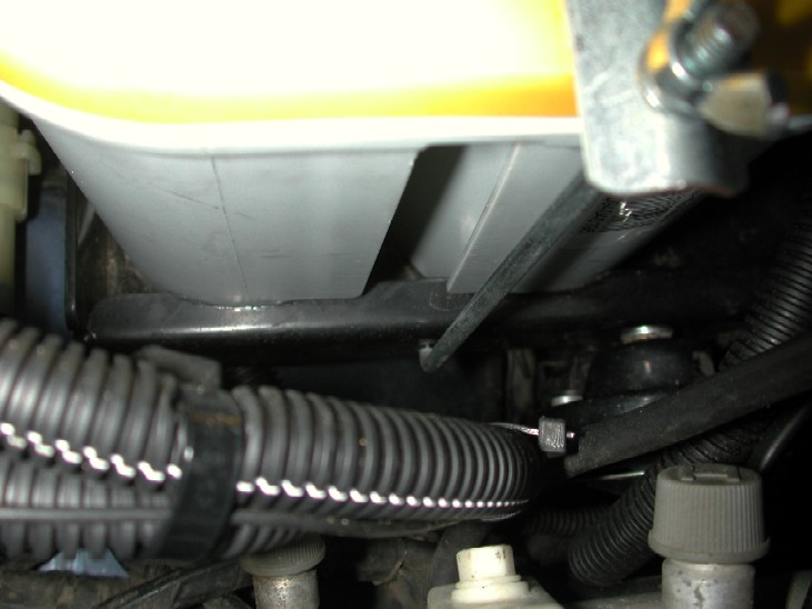
The Exide is very similar in size to the Optima, and If I did not already have an Optima, the Exide would have been the next choice, its very similar in cost and comes under the same BCI 34 grouping. The end plate will not fit / hold down the Optima battery, but it does provide a "heat" shield for the battery from the heat generated by the turbo, which is a HIGHLY recommend thing when installing a battery in this location. It is also recommended that you fit either a sealed AGM or Calcium battery as they are more resistant to the heat generated in that area by the turbo /manifold than a standard lead acid one, which have been known to "boil". The Optima won't fit snug with the end plate bolted to the tray in its designed way, so I simply turned the end plate around the other way, this allowed the optima to fit in the space and would provide a makeshift heat shield as well as a place to mount a hold down clamp for the battery, but this meant the Optima sat elevated one end on the bolt heads, so was not flat in the tray, to overcome this I simply modified the tray with a rotary file to fit the "shape" of the Optima better, below you can see where I removed some of the tray material.
Just this small amount allowed the optima to move away from the bolt heads the other end, and it makes it fit really well!!
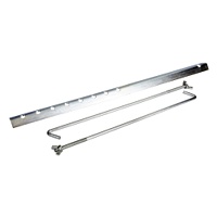
The battery now sits flat, level and neat in the ARB tray. Next was to find a way of holding / clamping the battery in position, this was done by simply purchasing a standard battery clamp like below..
These only cost a few pounds and can be bought from Halfords, Ebay and lots of other places, I picked one up at my local motor spares shop. The clamp although is adjustable didn't suit my needs 100% as the rods were longer than needed and so was the top clamp. So, to modify that I worked out where the clamp was going to fit (keep it away from the terminals) and cut the rods to the length I required and simply re-bent the "hook" ends with a trusty old hammer and vice!! On the heat shield end, I drilled a hole on the end plate.......
On the other end, I drilled a hole in the vertical side of the tray........
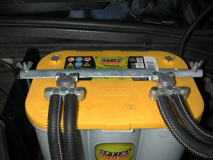
The top clamp was then cut to length to fit inside the end plate and look equal either side of the battery, a new hole was drilled to line up square with the rods, the 2 rods are different lengths, but they come to the same height at the top of the battery. The top clamp is simply held down by 2 wing nuts which makes it easy to remove the battery if needs be for maintenance etc.
As mentioned before, the clamp was positioned away from the terminals but still in a good place to hold down the battery firmly in the tray.
Next was to do the new wiring and to re-wire the winch to the new aux battery. Here is the wiring diagram I drew up for my new twin battery install........All cables between the 2 batteries and the winch / winch isolator and the split charge relay are 35mm2 ******The image below now reflects the VSR relay install, details at the bottom of the page******
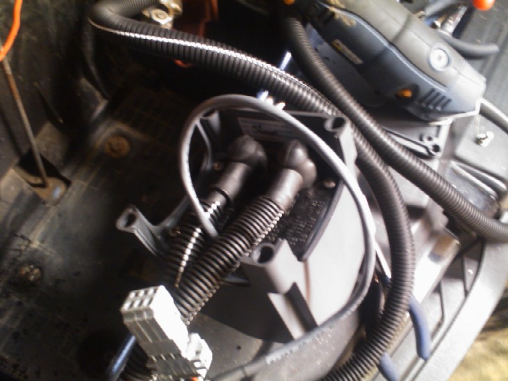
The wiring for the winch was from the starter battery and up to the winch solenoids, then back to the winch, but it also went through my winch cut out which was a single heavy duty Albright solenoid located by the main battery below..........
Now due to the ever decreasing space, the ideal spot for the split charge relay was where the winch cut out was, and because wiring the winch through the cut out and up to the new aux battery would need a lot more cable and provide an unnecessary cable run back and forth, I decided to move the winch cut out up onto the battery tray.... The Tray has a mounting position on its lower mount for a split charge kit / relay sold by ARB, this provided an ideal spot to mount the single Albright solenoid..
The solenoid was bolted to the tray, and the new battery cables made up and connected. Its not possible to connect the solenoid up with the tray in the car, or it would be VERY difficult, so all the connections were made including the 2 small wires which go up to the dashboard switch, these were simply extended across the bulkhead to the tray. Below is all the connections made before the tray is bolted back into the car.......
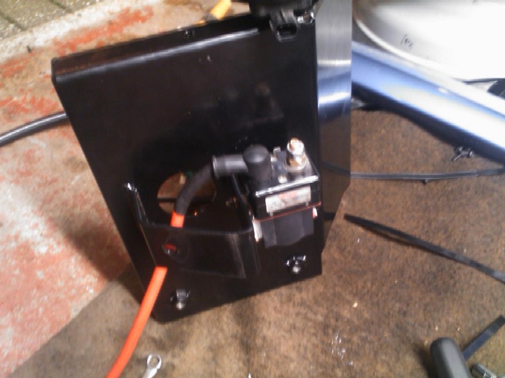
With the tray now fully installed, the split charge relay was mounted where the single Albright was.....
There is several ways to control a split charge system, lots of people have them on their caravans for example, and if you never intend to have a winch or wire one of your aux battery, a simple 12v 4 pin standard 30 amp relay with some 20 amp cable will do the same job as the heavy duty stuff.......BUT, with the winch potentially drawing of both batteries through the split charge, a heavy duty relay was used......Its called the X-charge and was bought from X-Eng engineering It's connected with heavy duty battery cable, a ground wire and a wire of up to the ignition supply of the radio as this does NOT go live whilst the engine is cranking, once the engine is running the relay connects both batteries together with the alternator. The TD5 uses a battery "sensed" alternator, so connecting up to the charge light won't work, details of that are all on the X-eng website.
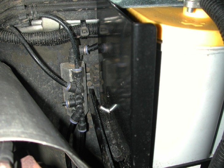
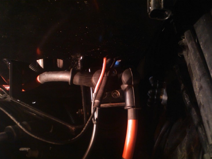
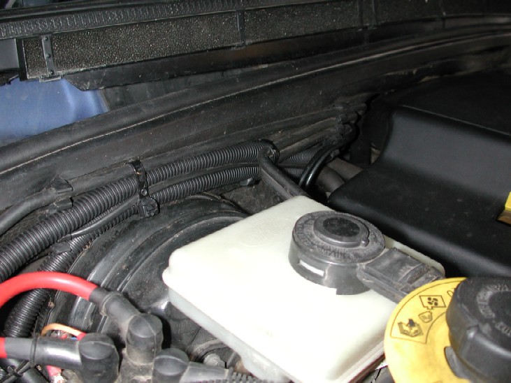
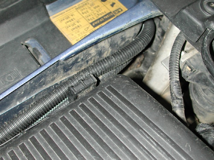
Next was to connect the winch to the new battery, so the positive supply to the solenoid pack and the cable from the split charge was run along the bulkhead in conduit tubing to protect it.
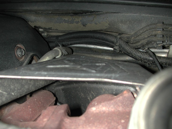
Its all tie wrapped to the pipe work which keeps it neat and tidy and out of harms way.....Next was the negative supply. Its regarded as far better to connect the 2 battery negative terminals DIRECTLY together and not to use the vehicle chassis as the ground return, this also applies to the winch which performs better when its directly earthed back to the supply battery. Now because there is already 2 large cables going round the bulkhead to the new battery, there really would not be enough room to get anymore cables that way, and it would make the cable run even longer than it needs to be, so the winch motor earth and the connection from the starter battery negative terminal were run again fully in conduit in front of the air con radiator tie wrapped to the pipe work and existing looms.......
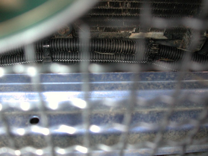
Up buy the aircon receiver/ dryer
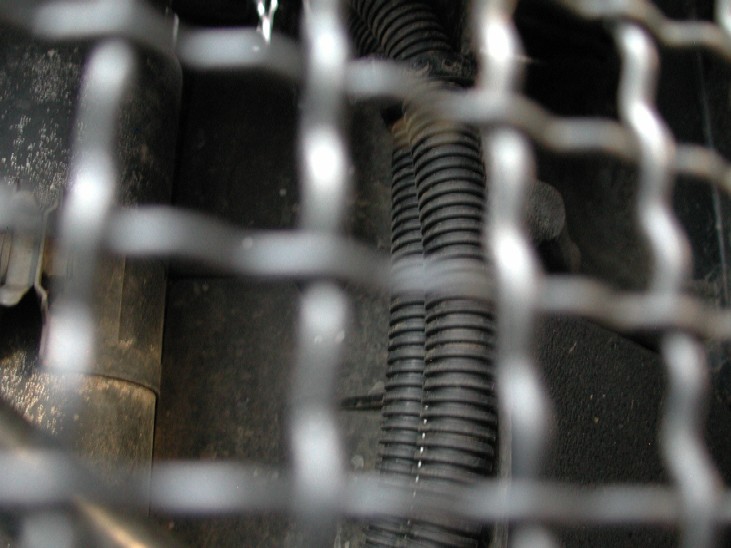
Round by the airbox and up to the new aux battery.......
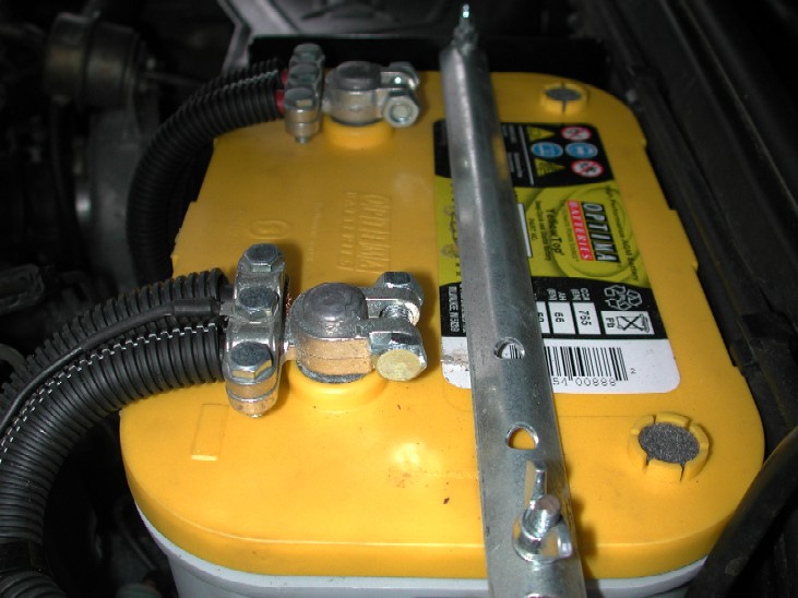
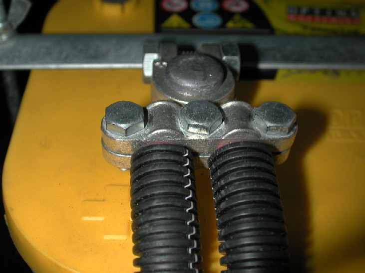
Finally was the battery terminals themselves, after lots of searching on the net, I finally found some that took my fancy, I did not like the single stud terminals as they can get messy when you add more and more circuits to the vehicle, the terminals I bought have 2 places each for heavy duty battery cable, and the bolts that clamp the cables can be used to neatly add ring terminals for other smaller auxiliary circuits later on.
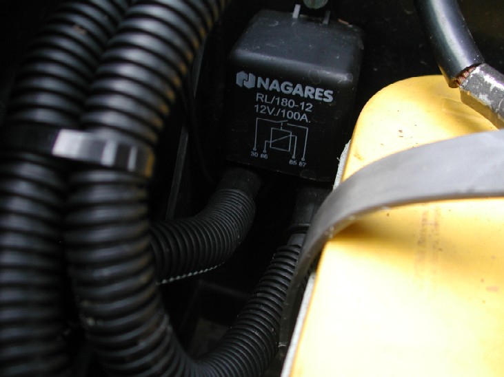
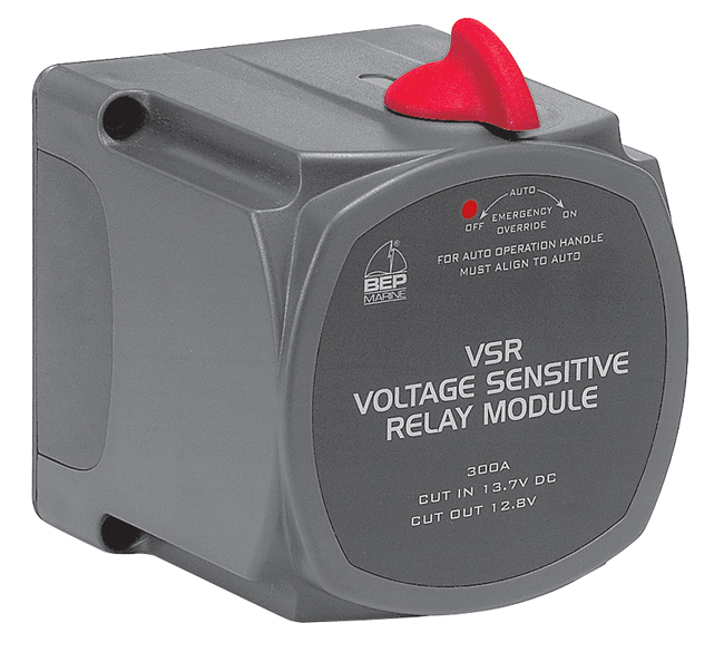
All the cables have been cable tied where needed to protect them from chaffing anywhere, all the 35mm2 cables run in the plastic convoluted tubing between all the connections. Overall I'm very happy how its turned out, the voltage at the new aux battery was within 0.2 volts of what's at the starter battery (14.62V) so its all working very well......In time I will add a battery monitor to the system just cause I can :o), but for now its simple and it works!! ***UPDATE BELOW*** Right, after LOTS of thinking on the issue I wanted to find something a little more heavy duty and a little more "clever" than the basic relay install, the reason for this was to make sure the batteries got charged in the best way possible. So after lots of searching in the "vehicle" electrical sections of websites etc I could not really find anything that took my fancy, so had a nosy around the Marine sites. I eventually came across this item made by BEP marine. As you probably know there is lots of stuff out there for boats that can be easily used on vehicles and it tends to be very high quality stuff because of the environment it gets used in, although on the negative side they usually command a high price.
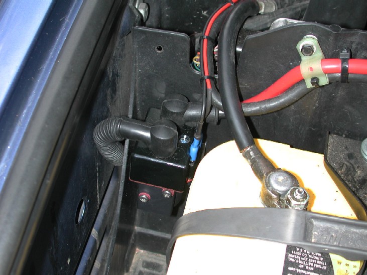
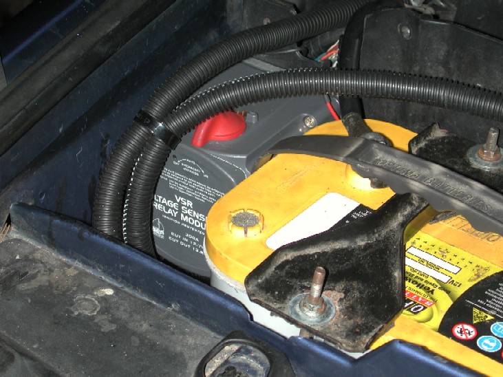
This relay is rated at 300A continuous and over 1200 cranking Amps so its well up to the job!!. Inside it contains some smart electronics that will charge the starter battery first and then switch automatically to parallel the aux battery when the voltages are correct. It also has a manual switch to physically isolate the second battery is needs be and best of all the switch can be manually turned to manually parallel the batteries so you can basically "jump" start yourself of the Aux battery. There is an LED indicator on the front so at a quick glance you can see if its all working ok. Its fully sealed waterproof unit and contains no diodes so there is zero voltage loss across it. If you wish to there is a facility to also fit a remote switch to parallel the batteries if you need to, and it will stay in this state for 10mins, if the voltage is good it will stay latched in, if not it will automatically isolate the batteries again to prevent both batteries discharging of each other. Overall an excellent product and exactly what I wanted, but if I'm honest a "little" pricey at over £120 but if it does the job it describes its def worth the investment to get the install right in my opinion. The biggest problem with it is its "physical" size, its huge compared to the standard x-eng relay I had originally installed and at one point I though it simply would not fit where I wanted it to, but after a little bit of shuffling stuff around...... First off I made up an aluminum plate to mount it on the battery box..
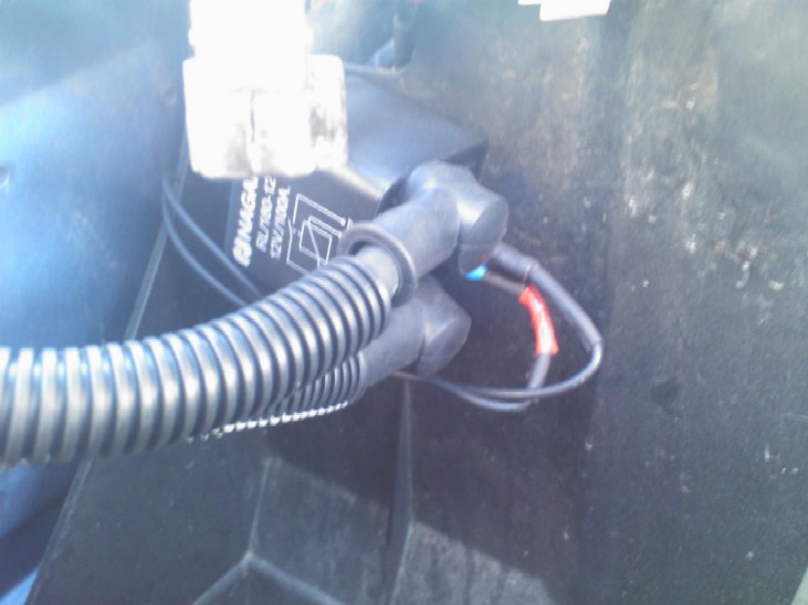
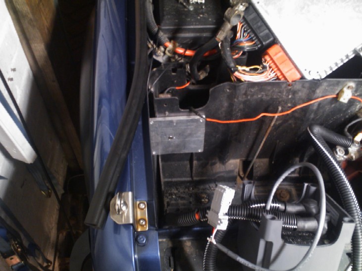
I had to remove a little section of the side of the battery box and also a few "webs" on the back face to allow the plate to sit flat Then wired it up to the same connections as the x-eng relay was, and because the VSR is "clever" and voltage sensing, it only needs a small earth connecting as well and that's it.
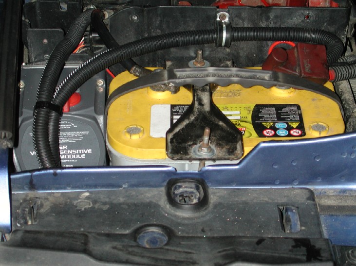
Because its a "modular" design, the grey lead comes already pre terminated to be able to fit a remote paralleling switch if you want to, but all I needed was the negative wire (black) from that loom for my install, so I remove the plug and connected the earth up to the ground that the x-eng had used that terminates just by all the other earth terminals on the car. As I said, it was a "tight" fit, but it goes in and that's about all you can fit in there, if I did not use an Optima battery there is no way it would fit in the battery box,
Very happy how its turned out and pleased with how its working, confident it will keep both batteries in a good state of charge and also now have the "backup" option with the manual switch should I ever need to jumpstart myself should the starter battery fail or be flattened ;o)
|
|||