![]()
|
Wading Kits...Axles, Gearbox, And Transfer Case Extended Breathers |
||||
|
|
UPDATED 16/07/2008 Breathers re-routed with the fitment of the Raised Air Intake. View that page for details !!!
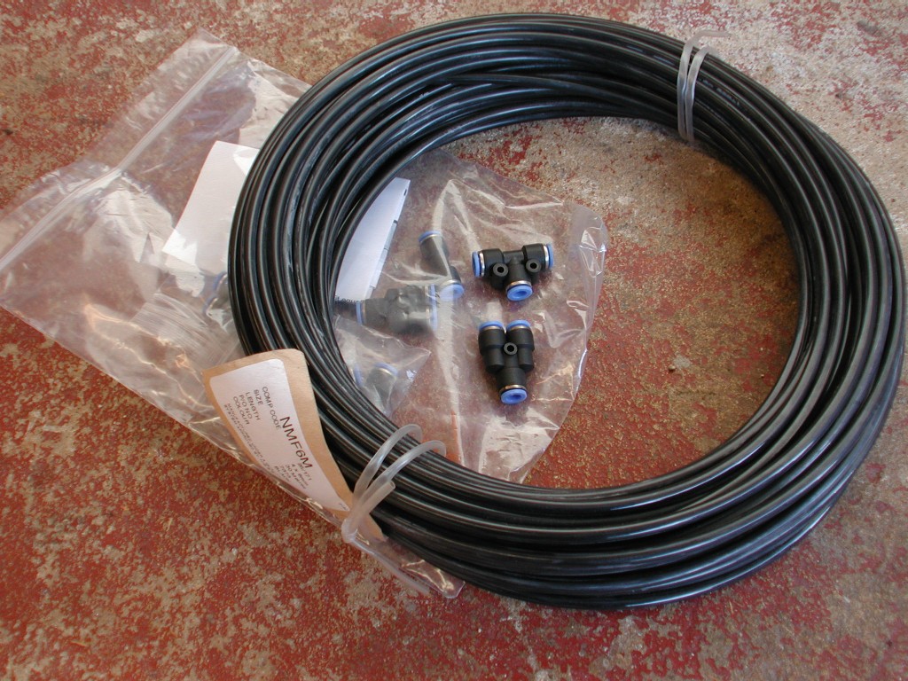
One of the most important modifications to your Land Rover if your ever going to take it for a swim is to extend your Axles, Gearbox and transfer case breathers to a "higher" location than the factory position. The Discovery 2's recommended wading depth is 20 inches, Obviously a Snorkel is the most important add-on if you wish to go deep wading, but its just as important to do the breathers to and better to be safe than sorry. 3 out of the 4 Disco 2 breathers are actually already high up in the engine bay, these are the front axle which is located at the top of the left bulkhead position, and the transfer case and gearbox are located together but not quite as high but on the right side of the engine just under the engine cover, left or right is referred to as you are driving the vehicle. The 4th breather for the rear axle is the odd one out, it does not come forward to the engine bay and it is only raised up under the rear left wheel arch and is the most likely one to be submerged if you waded deeper than 20 inches. Wading kits are available from many 4x4 sites and even on Ebay, but I chose to make my own to my preferences rather than a pre-made kit. The first obvious parts you will need is some Nylon Tubing. The standard breather tubing on the Land Rover is 6mm outside ,4mm inside diameter semi-flexible nylon tubing. There are many places to by this tubing in predetermined lengths, I chose to buy a roll of 30m in black for a very good price!! and then added some other bits to complete the kit. Although the tubing "is" semi flexible, it does not like tight turns in any direction, and because you will have 4 breather all at the same location, I looked for a way to join them together, so I bought some push fit pneumatic connections to help me complete this. I bought a few "T's" a couple of "Y's" , some 90* bends and some straight connectors to. This I thought would be more than enough for me to route the tubing exactly where and how a wanted it. Below is my roll of tube and you can see a few of the push-fit connectors as well
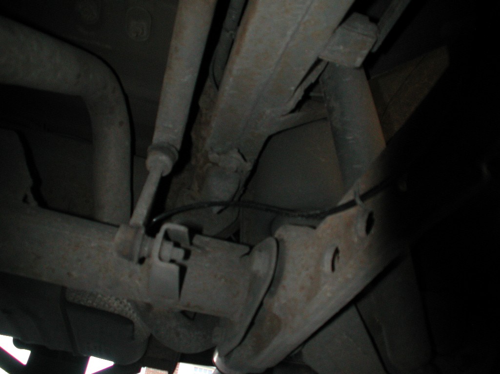
So to start with I decide to tackle the rear axle breather first, and get that up into the engine bay position. To do this you can simply pull out the old breather tube, I then fitted a new piece into the axle and ran a length along under the chassis tie-wrapping the tube into place together with some other tubes / pipes that run along under the left hand side where the SLS compressor is on vehicles fitted with Air suspension. I originally was going to use some of the connectors I had got to route the tube in the different directions it takes up to the engine bay, how ever I decided in the end it was flexible enough and a better idea to have one long run of tube.
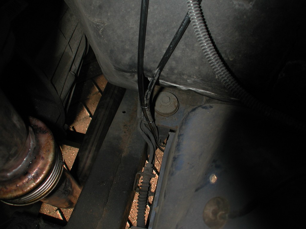
The tube exits the axle and is tie-wrapped to the suspension arm as per the "original" factory breather, then runs along the chassis up to the engine bay. Make sure you leave some " slack" in the pipe to allow it to stay connected when the axle articulates if you go offroading, the easiest way it to "loop" it up into the rear left wheel arch just like the original one. If you take a good look at the factory breather before you rip it out, you will see what's best and how its routed. Once the tube for the new rear breather was up to the engine bay, I tie- wrapped it to the front axle breather like below
Now I could join the rear axle breather to the front axle breather that is already at the rear left bulkhead in the engine bay. I cut some of the length off the front axle breather as it was not needed and so I could make it look neater.
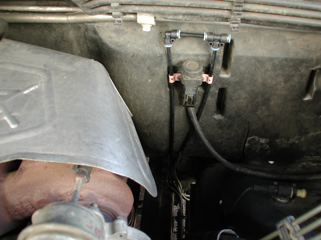
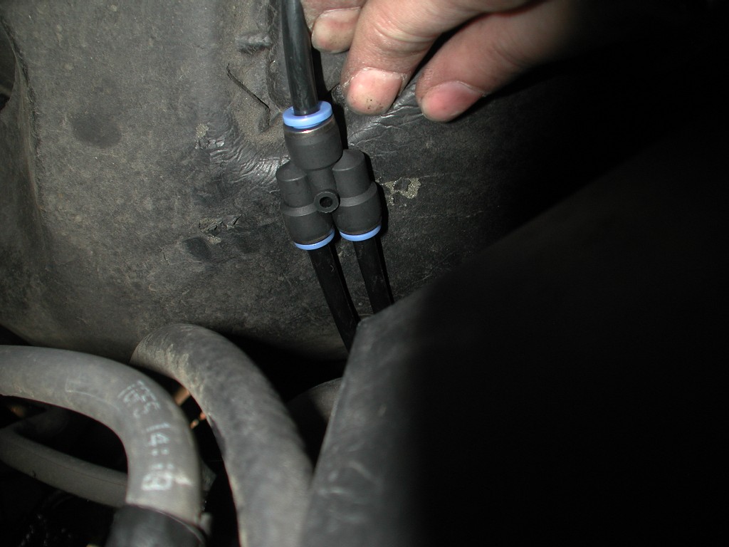
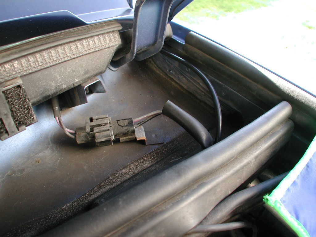
Here you can see I used a 90* and "T" connector to join them together, I then used 2 P clips to hold them in position and fixed it using the same screws for the fuel reset switch. Now onto the transfer case and Gearbox breathers. These are located at the back of the engine to the right hanside and are just "hooked" over the fuel pipes from the factory, its a bit poor really as they were chaffing on allsorts of other bits. To see them clearly just remove the engine plastic cover and you will see them tangled in there. They are actually clipped together, this made it easier to modify the routing off them. I had already cut of the loops form the end previous to doing the job, so I have no picture of that, but in the pictures below you will see enough for you to know what's going on. As I stated earlier, instead of having 4 tubes at a high level I decide to join them together so i only had 2 to route up the "A" pillars, (1 each side) Below you can see that they already run together, so it was easy enough to cut them level with each other and then fit a push fit "y" connector
Another length of tube was then added long enough to reach up the A pillar to the top of the windscreen trim, on the drivers side its simply pushed behind the master cylinder and is held firmly there by the firewall insulation. It then goes through the heated windscreen wire grommet on each side and up the "A" pillar. Here is the passenger side again with the new tube added to go up the A pillar.....
And through the heated windscreen grommet, the same on both sides. Make sure its routed away form the bonnet hinges......I also tie-wrapped it to the wiring here to hold it in position.
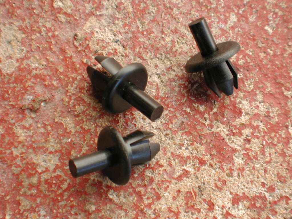
No we have 2 tubes (1 each side) ready to go up the A pillar. To remove the "A" pillar trim, you simply push out the centres of the plastic trim rivets, unfortunately you cannot retain the centres, so its a good idea to have some new ones ready for when you refit the trim. I never got mine from Land Rover as I have lots of bits and bobs in the garage including loads of trim stuff I have accumulated over the years. I actually used Vauxhall Wheel arch liner rivets, they are almost identical to what you remove. below is what they look like, you will need 3 each side.....
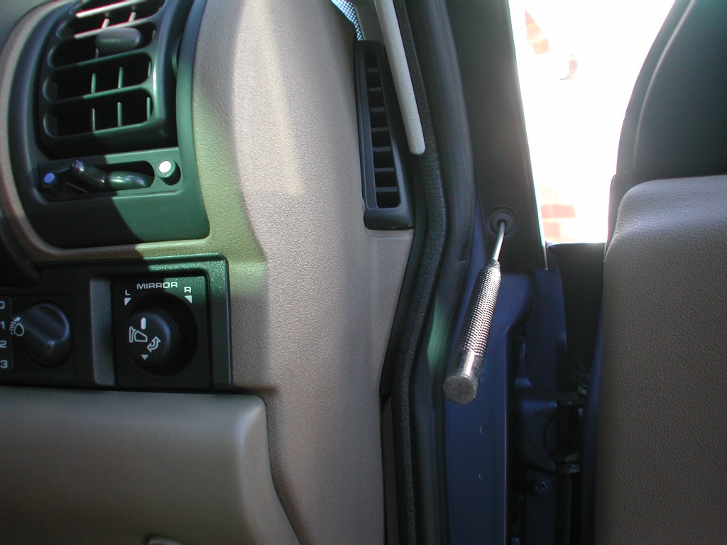
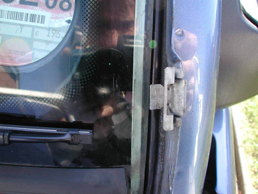
To remove the trim, punch out the centres on the 3 rivets, prise out the remaining body and then unclip the trim towards you "carefully" as your standing at the side of the car.. with the door CLOSED , There is 3 metal spring clips on each side.....see below with the trim off
The amount of dust , dirt and crap under this trim was quite a surprise, so it was all cleaned of before I took the picture !!! Now you can route your new tube up under the lower windscreen scuttle panel and up the "A" pillar between the Windscreen glass and the 3 metal clips, its a super snug fit and was made for the job!!!.....can you see it ??
Once your tubes are in position, at the top of the windscreen they can "poke" out between the "A" pillar trim and the rain gutter, you really need to add a bend or Hook shape on the end so water does not get in, I pushed some 27 amp wire down the tube to stop it kinking / collapsing when I bent it, I may have to add some heat to help it ....It got dark at this point so I'll add more pictures soon then you can begin to re fit...... Refitting of the trim took me a while !! to get it to insert in all 3 spring clips, take your time an be careful, its fiddly and tough, but you really don't want to have to buy new trims !!. Do it with the Doors CLOSED, and make sure its fully clipped in position before you re-fit the plastic rivets back in the door shut...
|
|||