![]()
|
Roof Rack -- "Additional lighting" (Updated 13/03/2008) |
||||
|
|
Ever since the days of the Camel
Trophy, adding lights high up on the roof of Land Rovers has just become
the "done thing", although they do actually serve a very useful purpose
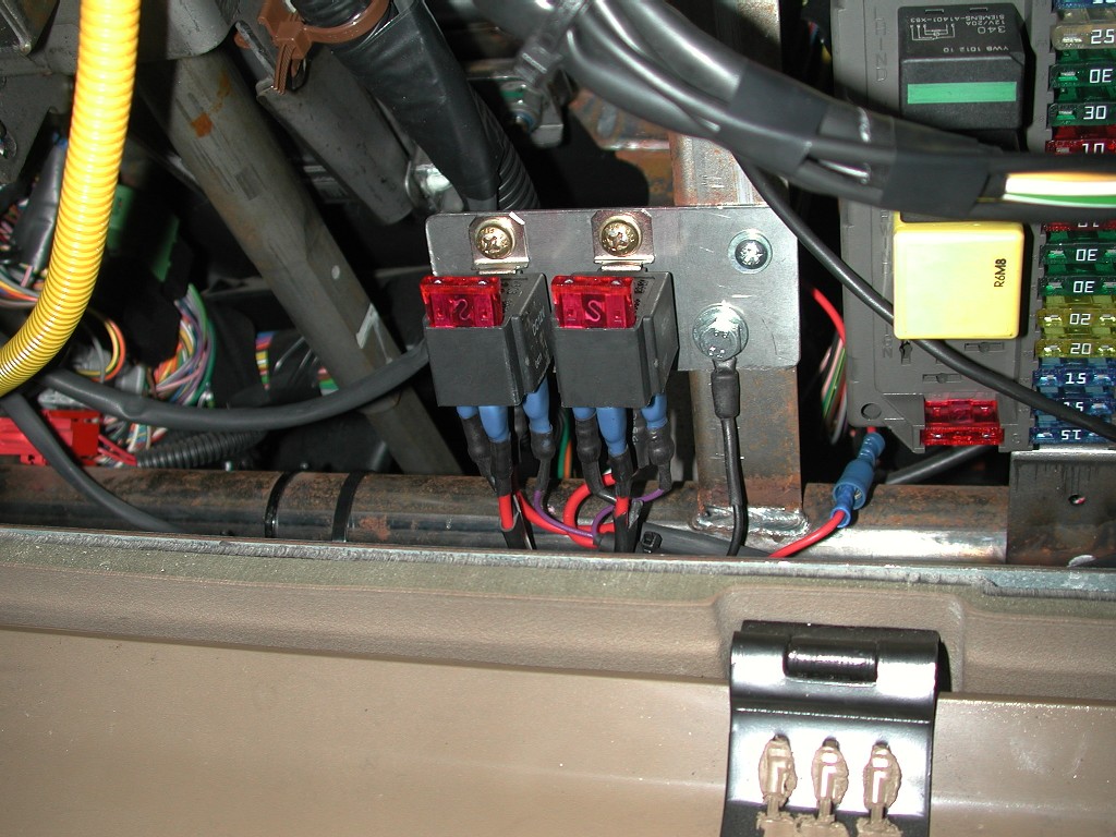
when on country lanes or off road, and look cool to!! There is so many different types of lights to choose from in many different shapes to. For me personally I prefer the look of rectangular lights as opposed to round when high up, this is just my opinion. Also you have to decide what type of lights you want up there, there is a choice of spot / driving lights that will assist in long distance view at night, fog lamps that would give a closer wider spread of beam, and also work lamps which will defuse the light to a large wide area, but will give no better distance than your standard headlights / main beam already do. Some people fit a combination of both, to get both a wide spread and a long distance, but I chose not to do this as I wanted all 4 lights to be the same. Depending on what lamps you choose, there is different rules and regulations for additional vehicle lighting that you "should" adhere to. If you only ever intend to use them "off road", then who cares, fit what you like up there!! Whether roof lights or not were needed by myself, I though I would add them because as well as being useful, that look dam good to!!. Again there's a choice here, whether to add the high mounted lights to a roof rack, or fit an additional "light bar" and mount them to that instead. I originally made a light bar out of an old roof bar that clamped to the roof rails and could easily be fitted and removed in minutes, how ever this was before I got my Large expedition roof rack, so I changed my mind and decide to fit them to that instead. This posed me another issue, once the lights were on the roof rack, I had to get the wires up to them, a common way to achieve this is go up the A pillar, usually in conjunction with a snorkel, but I have no snorkel (yet...!! ) so this was going to be a bit of a problem. There is also the option of drilling a hole into the roof somewhere and running cables that way, but I again could not do this as I don't keep my roof rack fitted all the time, so as well as getting the wires up there, it had to be neat and as much as possible "out of site" AND easy to disconnect when I remove the roof rack......pfft!!!. The lamps I originally purchased were Wipac work lamps, I felt at the time they would give a good spread of light when fitted high up. When choosing your lamps, be sure to work out the current they will consume as this will affect the size of cable, relays etc you will use. I chose to use 4 lamps at 55watts each, so in total they would consume around 18amps at 12v, this means I needed a cable that would cope with that rating + the added extra you include for safety. So 25amp cable would be ok and a single relay rated at 40 amps would be ok as well, how ever it is advisable to fit at least 1 relay per pair of lights, so 2x20amp relays would be the Ideal You can use the normal calculation to work out what you will need, eg:- Amps = Power / volts or I=P /V this equates to 4 x 55watts = 220w, so I = 220w /12v = 18.3333amps. RELAYS So, I know what size cable and relays I needed, now I had to decide where to put them ?, obviously the engine compartment has plenty of additional space where 2 relays could be easily mounted, but I decided if I could I would fit them inside car to help protect them from corrosion etc and be able to get to them easily. Inside the pull down cover to the internal fuse box, there is actually a lot of space you can utilise. This is where I made a small stainless steel plate and mounted it to the structure in the space, there is even some threaded holes that are just perfect to use for attaching the plate to the car
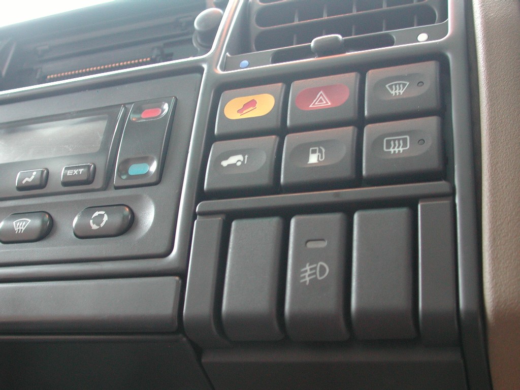
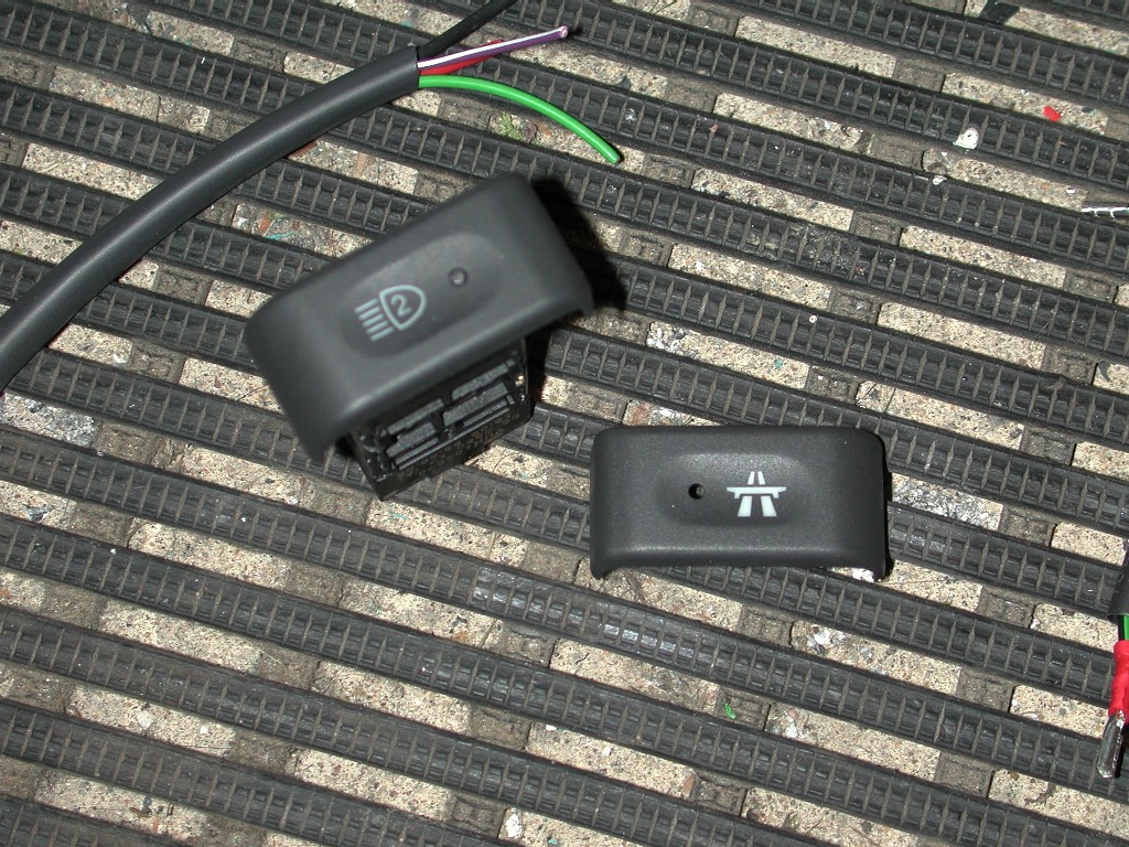
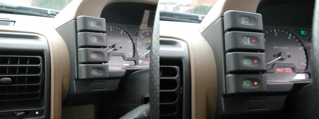
As you can see I used relays with "built in" fuses, they are about twice the price of standard relay's , but this makes the wiring a little easier and saved me having to wire in messy "inline" fuses. The plate is bolted to the car, and the relays come with their own holders and simply clip onto them, then they are bolted through the plate. This structure in the fuse area is actually a good earth as well, so you can see it was a convenient place to earth the next part of my install, the switch assy. DASH SWITCH The option for a switch is an endless choice as with lights etc, but I don't like non factory switches hanging on the dash, I like to keep it as neat as possible. This posed a problem as there is no spare switches on my dash, I couldn't even use the genuine Land Rover additional lamp switch as this is a non latching switch.( see spot lights page). So to get around this I decided to use some Discovery 1 parts as they have switches in some different locations to the discovery 2, Land rover did not produce an additional lamp switch for the series 1 Discovery, so the next best thing was a Front fog lamp switch. This is a latching switch and could be wired up with the relays and dashboard lighting to give the closest I could get to the factory look. The Discovery 1 front fog switch is located in a carrier assembly where the coin tray is normally fitted on the Discovery 2, so after looking through the parts catalogue for the bits I needed, I then ordered them from my Local dealer ready for the install This included, the carrier assembly (available in 2 or 3 switch mounts) I bought the 3 switch carrier to allow for 2 further "gadgets" to added later if needed, 2 front fog light switches, and some switch blanks. Below is what it looks like fitted in my Disco 2. The carrier simply clips into place where the coin tray was, Its the same shade of colour as the existing dash (ash grey) and also follows the contours perfectly........nice hey !!
I fitted 1 front fog light switch in the middle for now, and this will be used for the Roof rack lighting, in fact the fog lamp symbol on the switch is quite appropriate for high mounted lights as it points down. The switch has 5 contacts, but we only need 4 of them, power, load, lighting and ground.
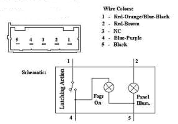
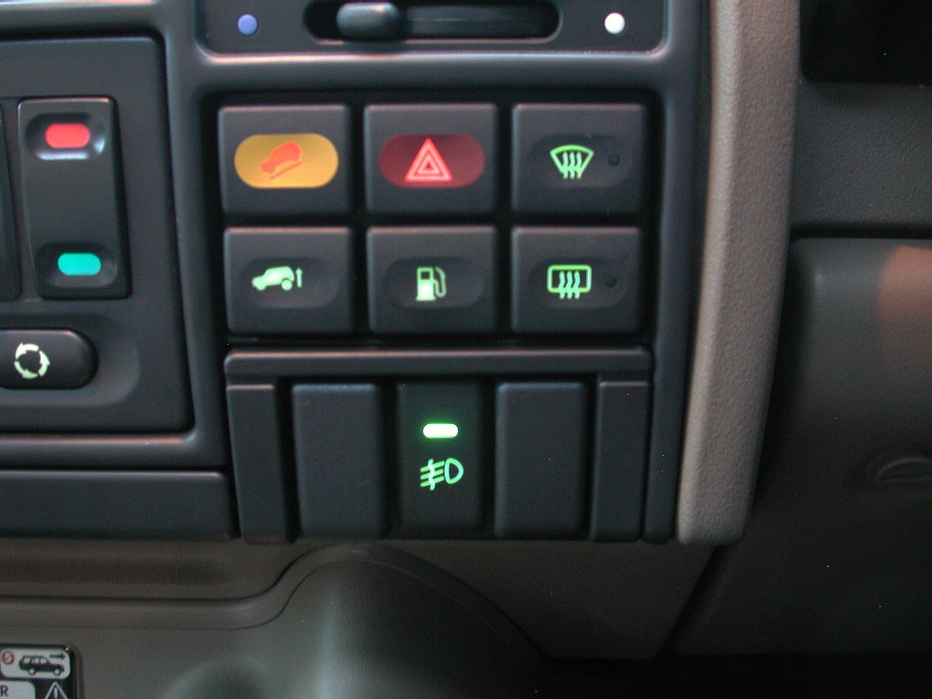
Now I had to make a loom to connect the switch to the relays, and into the existing car circuit for a 12v source and dash lighting. You could wire the switch directly to the battery, but that's to far away and I decided to find an Ignition "on" 12v supply inside the car. There is many to choose from, and as its only a switched source (no high current) it could come from anywhere. In the end I fed the switch with an ignition on "live" from my power folding mirror circuit, as this is only really used to fold the mirrors in/out and mostly you would have stopped, or be leaving the vehicle, so additional loads on the circuit would be minimal, also my loom to the relays had to go in that general direction as this was where they are mounted, which is close to the mirror fold switch. I chose to use colours as close as the factory ones that you see in the diagram above. Pins 1 and 4 are the switch "action", Pin 2 is switch illumination, and Pin 5 is ground. You cannot buy the plugs to fit these switches, so the best and easiest way is to use 2.5-2.8 mm female blade crimps, I would also strongly advise you cover each crimp in heat shrink as I did to stop any chance of the crimps touching when pushed onto the switch as they are very close to each other. So I now had a 12v ignition source connected to Pin 1, to connect up to the dash lights, I simply spliced of the "original" front fog light switch in the dash surround. This is Pin 2 on both the Discovery 1 and 2 fog lamp switches. Pin 5 is the ground you saw earlier that runs to the mounting plate for the relays, and finally Pin 4 connects to terminal 86 on both relays. The wire you use for this loom can be small 5 amp wire, or even smaller as its literally a 12v signal to the relays, it carries hardly any current, I again used some wire left over from the Roof harness I bought for the Satellite Navigation install. The whole loom was heat shrinked to help protect it and to keep it neat, you can see the black heatshrink in the relay picture earlier. Now I simply routed it to the relay's avoiding any sharp edges etc. Below the switch is selected on so you get the green indicator, and the dash lights are on to, so it all matches and looks very factory!!
UPDATE 13/03/2008 Well, even after completing the install on the roof rack lighting, Although I was very happy with what I had done, I was still always "pondering" whether or not I could do anything different. Above you can see I used a Discovery 1 switch and carrier assy because the Disco 2 Additional Lamp switch is "momentary action" only, However after some brain storming I came up with another solution that I could try. I studied the wiring diagrams for all the dash switches, and in particular the only 2 "latching" ones, these being the Rear wash wipe and cruise control switch. It quickly became clear that the rear wash wipe switch would not be suitable as its wired differently and the action is still controlled by the BCU, plus the rear wipe switch also does not have a "indicator" light telling you its on or off. So this left one option and that's the cruise switch. I ordered one of these from the dealer and then went onto the next part of the plan. All the Disco 2 switches are basically the same, they just differ as far as latching or non-latching and whether they have an indicator light built in as well, but the face plates with the different symbols on, simply "unclip" off, so this means you can change them around. So I already had a spare additional lamp switch, so I unclipped the face from both the cruise switch and additional lamp switch and swapped them. I now have a "latching" additional lamp switch with and indicator light to. (below)
I then wired up the new switch with a new loom and female crimps exactly as before, the disco 2 cruise switch pin arrangement is exactly the same as the Disco 1 fog lamp switch. Pin 1 = +12v, Pin 2 = Dash Lighting, Pin 3 = (un-used) Pin 4= Load, and Pin 5 = Earth.
Then it was simply a case of connecting this new loom exactly as I had previously done with the Disco 1 switch. So now I have 2 additional lamp switches on the dash, One controls the front spots using the factory wiring through the control unit (momentary action), and also another one below to control the roof rack lights (latching action). This fills up the binnacle surround fully on the left hand side now, It also frees up the space where the ashtray goes and where I fitted the "original" Disco 1 fog lamp switch. This will either enable me to refit the ashtray, or put in place the next little project. (coming soon)
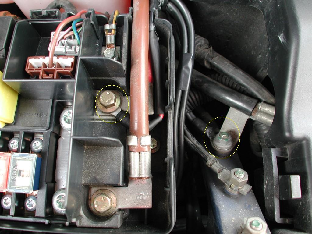
This may also be of use the those who have factory spot lamps that are a bit "hit and miss" as to whether they work or not. They are known for being a little unreliable, so in the worst case scenario, you could re-wire them through a modified latching factory switch as I have done here, that way you would still have the choice as to whether they come on or not with full beam. LAMP SUPPLY (to relays) So now I had a new light and switch to play with, the next part was getting a "high" current supply to the relays to actually supply the lamps. There is not one inside the car, so you will have to run one in. In the end I used twin core Red / Black double insulated 14amp truck cable and would run one twin cable to each pair of lamps. I could not be bothered working out roughly how much I would need, and didn't want to run out half way through if I got my estimate wrong, so to give plenty to play with I simply bought a 30m role from a local auto electricians which cost around £25. To find a supply, well you could simply run it directly from the battery, however with the up and coming additions of other mods, this would mean lots of ring terminals off the battery posts for me, you could off course fit and additional fuse box, but I could not find one that had a single supply with separate feeds of it, so with this in mind and again for neatness, I took the supply from inside the engine compartment fuse box as there is also places to connect to in there. Right next to the front of the fusebox is also a factory chassis earth point stud, this made it easy to earth the 2 new twin supply cables to.
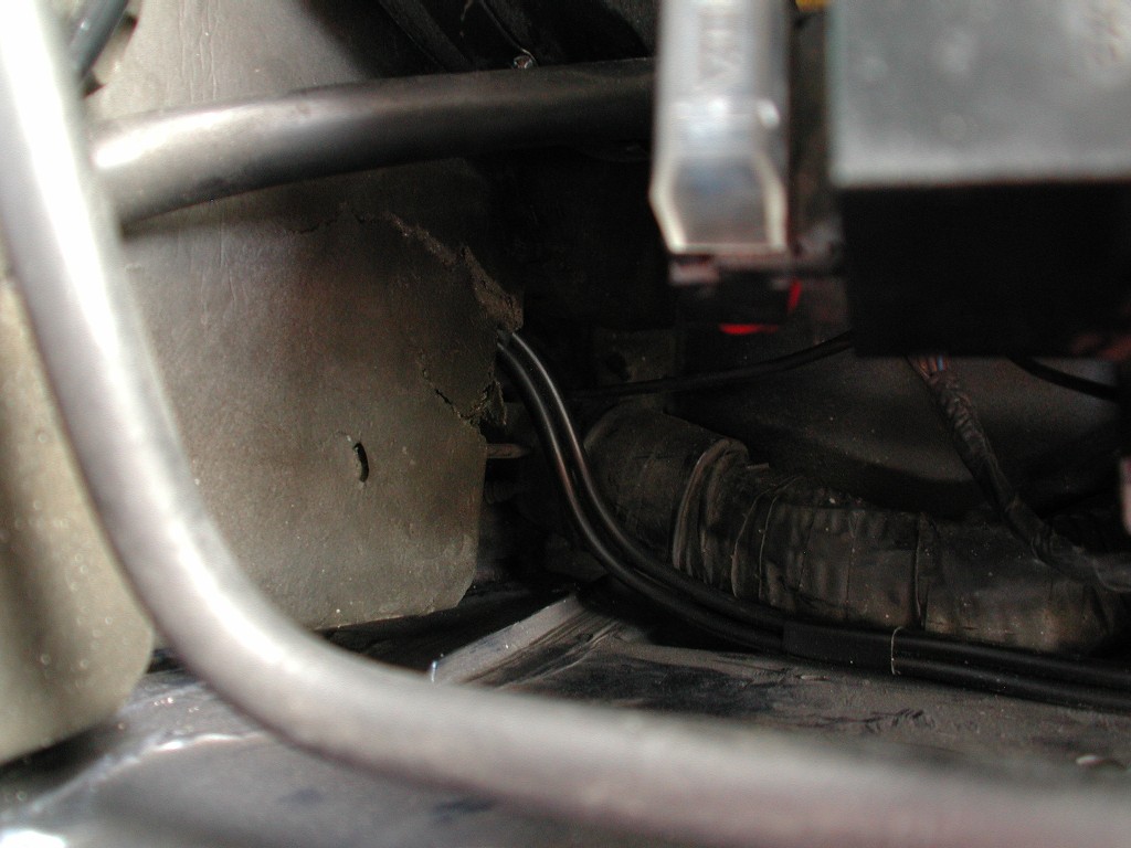
The 2 cables were tied neatly together, they enter the fusebox through the existing cut outs and simply run around it and towards the bulk head on the drivers side where you will find a large rubber bung / grommet, its underneath the bulk head soundproofing and is easy to get to, and also comes out in the car behind the internal fusebox. This was very pleasing as its really simple to add additional wire for anything into the Discovery 2 from the engine compartment without drilling new holes or fighting for hours trying to feed new wires through existing grommets and looms. I used a set of hole punch pliers to cut a neat hole through the bung and then fed the wires into the car and then up to my relays.
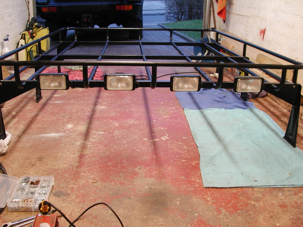
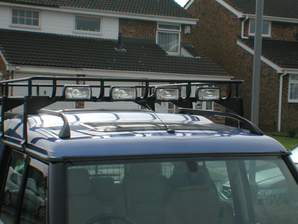
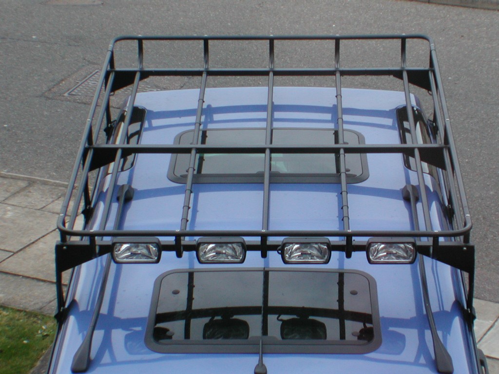
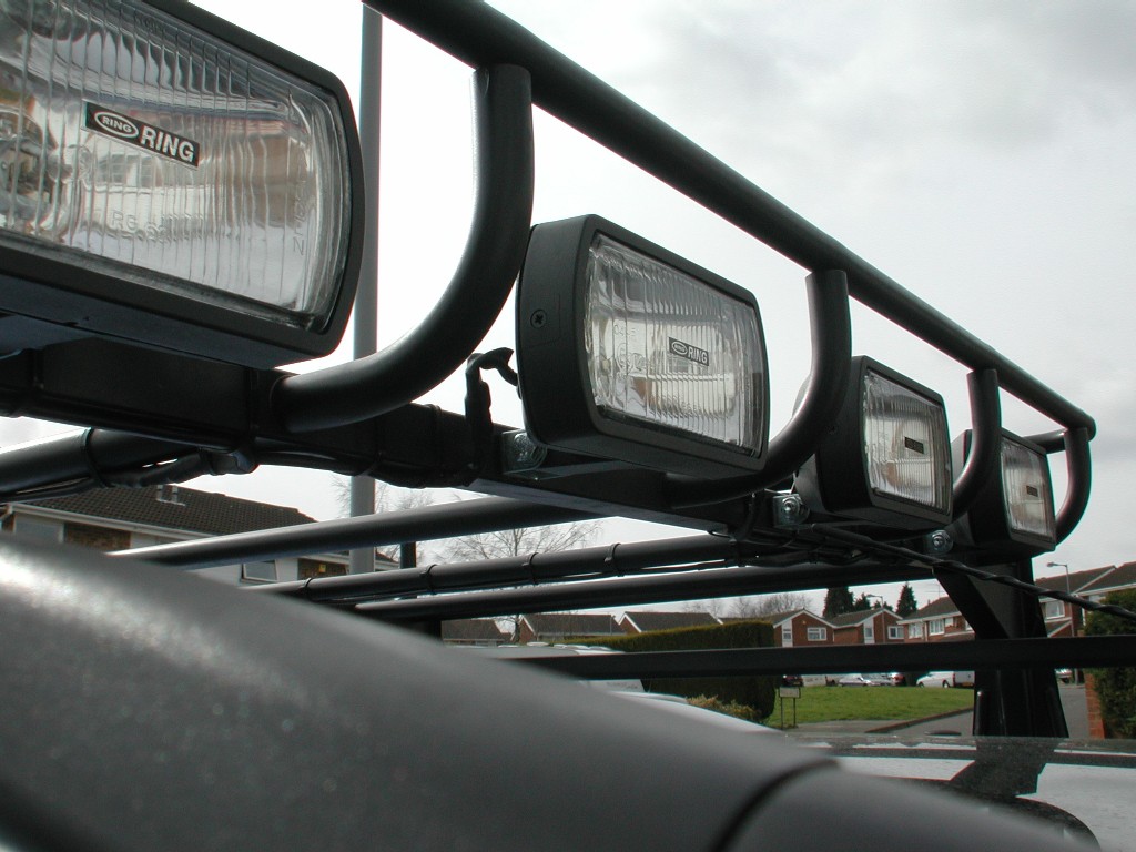
All ring terminals and crimps are also heat shrinked to give more protection against corrosion etc, it also looks more professional to in my opinion, its a shame Land rover don't do similar things in the factory !! LAMP SUPPLY (from relays) From the relays, the cables run down behind the kick panel in the drivers foot well, there is also several factory earth points (studs) here, so that's where the cables are earthed, they then run along under the black trim by the sills, up and over the rear wheel arch and then behind the side trim in the boot where the cubby boxes are (or 7 seats if fitted) and then arrive at the 2 grill panels in the rear trim. LAMP MOUNTING The lamps I originally fitted were WIPAC work Lamps, these give a wide spread of light, but after testing them out on the car, they don't really give that much more distance which is partly what I wanted to achieve, so since taking these next few pictures I have replaced the lamps with 55w Ring Driving / spot lamps, They are a little bigger than the work lamps but are mounted in the same place, and these do give more distance at night. The New lights are pictured at the end of the article.
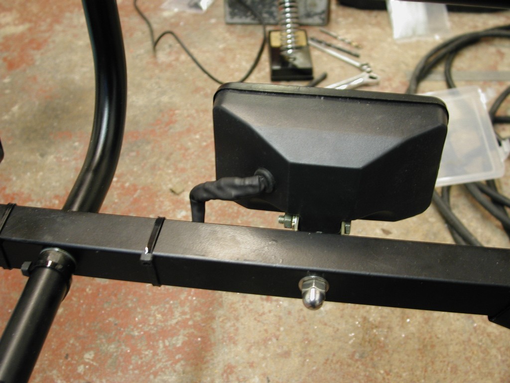
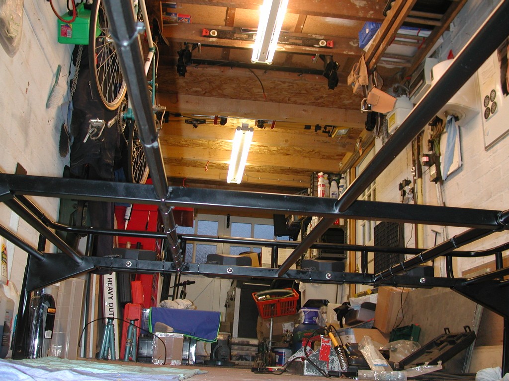
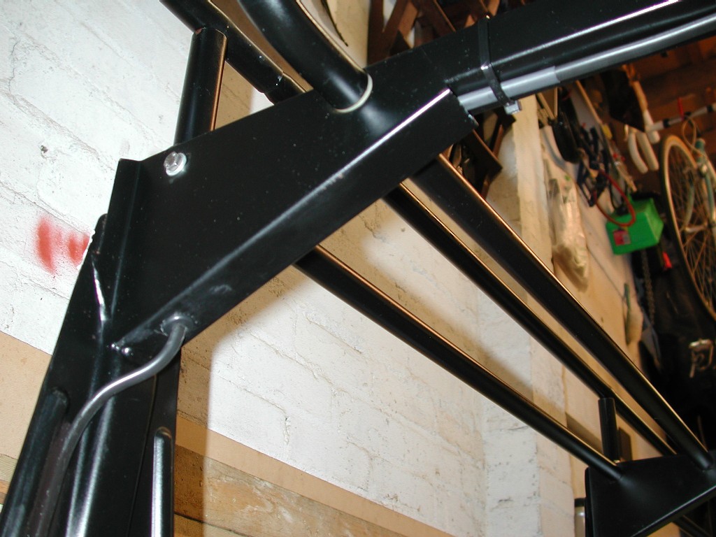
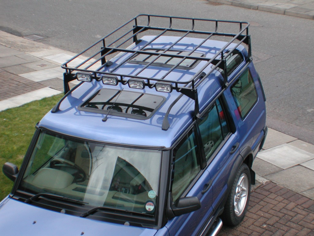
I looked at lots of pictures of other Land Rover with lamps mounted on the roof racks, and there is a LOT out there, I could not decide initially whether to "hang" the lamps from the front cross rail, or as you see them here go "through" the rail front to back. Hanging the lamps underneath the rail does give 1 advantage in that the outside 2 lamps can be swivelled on their mounts outwards slightly to "widen" the spread of light, but they look a little "lost" just hanging there and break the "neat" line of the roof rack. This is just my opinion and you should fit your lamps where you want them. So in the end I decided to go "through" the rail front to back and the lamps now sit nicely in between the spaces in the luggage rail, this may also provide "some" protection when off road. The outside 2 lamps could still be directed outwards if I add small wedge shape packers under the mount, I may still do this but will continue as they are for now. With the lamps mounted in this position, they do actually encroach into the load space slightly, how ever because of the curved rails at either end, its not really possible to fit items right up against the rail, so with this in mind I will be adding a small stop or beam behind the lamps to stop them getting knocked. They do not come further back than the front cross rail, so when the roof rack is "decked" it still won't pose a problem as there is more than enough space for what I need to put up there.
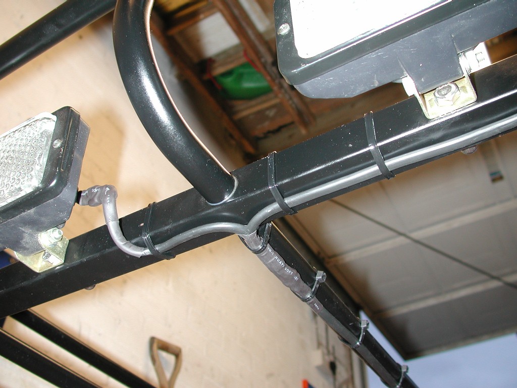
LAMP WIRING With the lamps now mounted, it was a case of me having to now decide finally where the wiring would go and how to get it into the car and down to my relays in the front fusebox. Remember I want it as discrete as possible, neat and tidy but also be able to be disconnected to remove the roof rack with the lamps. There will be 2 twin 14amp cables coming up to the lamps, each twin cable is then spliced to another piece of the same cable and in turn power 1 pair of lamps. The cable that I used is black in colour and is double insulated, of a flat design and obviously waterproof, so there was no real need to add any plastic trunking or conduit as this would be also make them a lot bigger to run to other locations. With that in mind and because I now had a plan as to the final route, I simply cable tie-ed the cable to the underside of the longitudinal rails and then along underneath the square cross rails where required. The longitudinal rails actually sit slightly lower than the cross rails, so when the deck is added this wont be a problem, for the cross rails, I may need to come up with another way, or simply cut slots in the deck where the tie wraps are, this will stop the deck rubbing on them and make them possible to change if they break once the deck is in place. Some people, as I did with my original light bar, drill holes and run the wires "inside" the rails, but because of the design of this rack this isn't really feasible for me, and I like to avoid drilling anything Land Rover as it will help it rust even more quickly!! Below you can see the cable for one pair running to the back of the rack, and the spliced joint at the front to feed 2 lamps. The spliced joint is soldered, insulation taped and then covered with heat shrink to protect it from the elements.
And the other pair.........
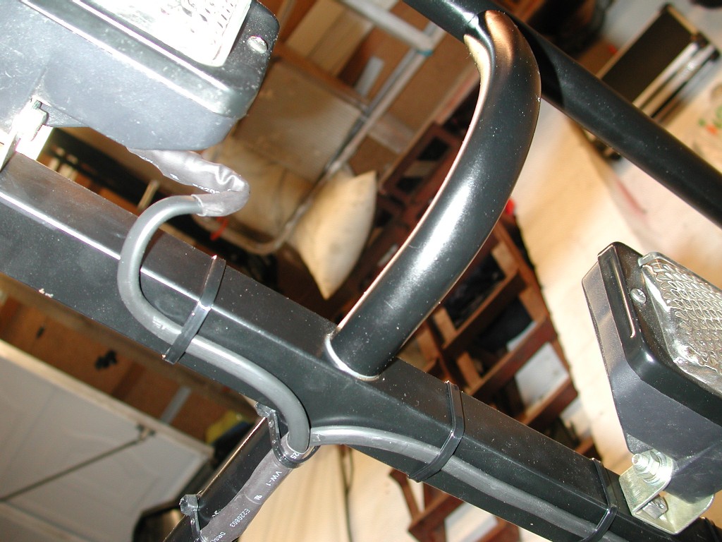
All of the connections at the lamps use standard female /male 15amp blade terminals, and are then covered again with heat shrink to protect them. It will be a a bit of a pain to replace a bulb as the heat shrink will have to be cut off to get to the connections, a new piece is simply enough to add, and I have already done it 4 times when I replaced the Lamps ,but overall I consider this a penalty worth paying to have the connections covered from the elements, and it looks neater to. Both cables run along the front to back rails between each pair of lamps,
they then go outwards along the rear cross rail to each respective side of the rack, "inside" the rack feet and exit through a hole and grommet I did actually drill !!
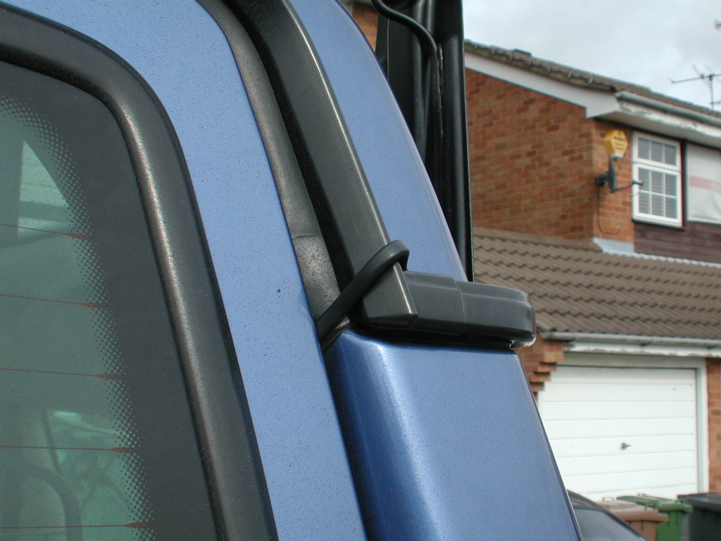
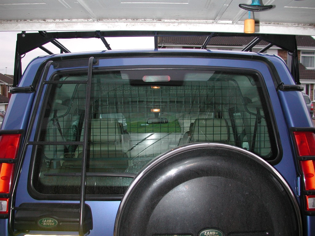
The cable is then silicone sealed with Aircraft grade Black adhesive silicone to the inside of each rear leg, and runs to the bottom of each rear foot and there I left a suitable length to connect to the car side of the install. FINAL HOOK UP With the roof rack fitted on the car, the cables that are now by the rear feet, simply lay in the gutter and stay roughly in the shape formed as the cable is quite stiff.
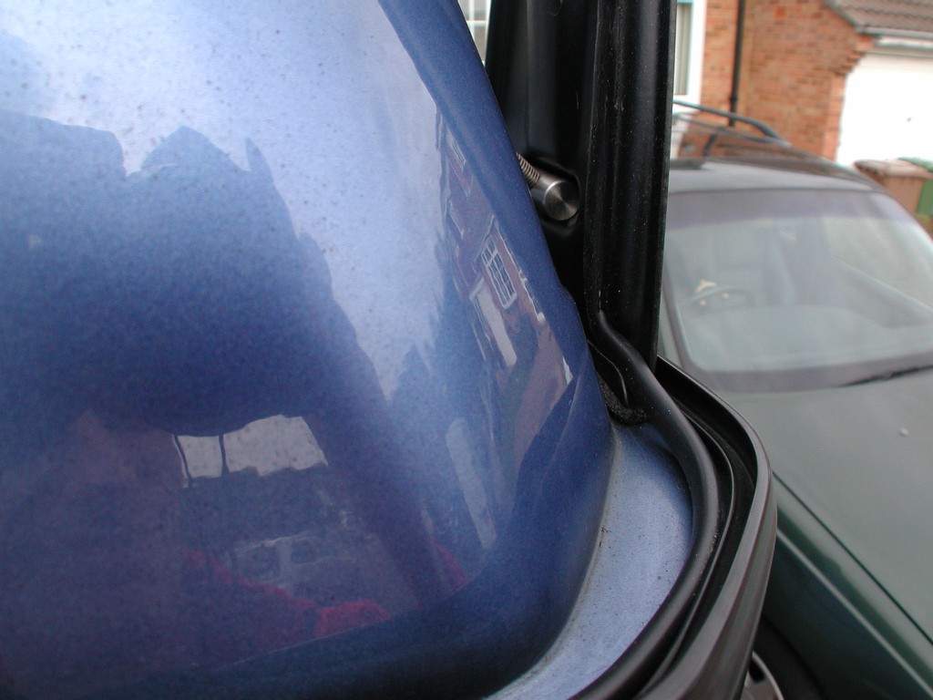
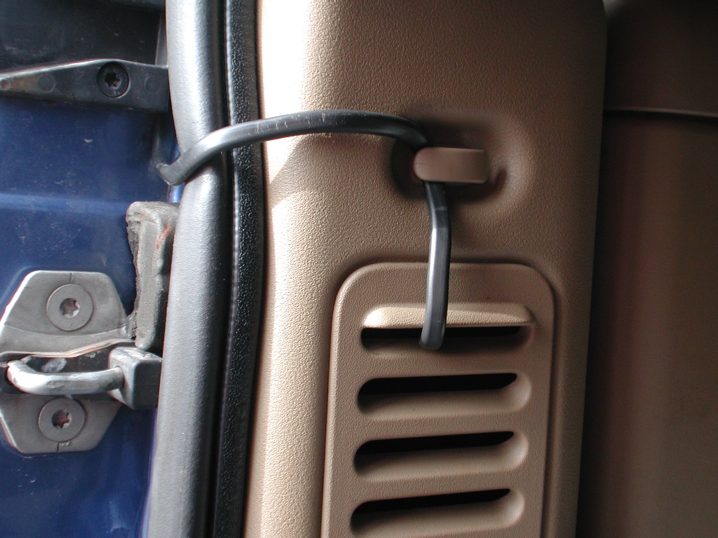
Once they get round to the rear door, the only option I had really to keep it "semi permanent" was go over the gutter and down in between the boot rubber and rear door aperture.
And the same for the other side. Its not the "best" option, but it works and gets the cables into the car without drilling any holes, and its not that visible really, so I'm quite happy with it for now. I may in time come up with another solution, if I do I will update the pictures etc. Below is a view from behind and the cables are quite discreet really.
On both sides the cables simply go over the top of the rubber, and conveniently clip nicely into the rear side cargo net clips, then down into the grilles and simply connect to the power cables coming from the relays using crimped 15amp butt connectors. So to disconnect the cables from the car takes 2 mins, by simply unclipping the grilles and disconnecting the butt connectors.
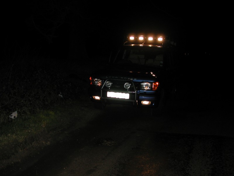
It's by no means a "perfect" solution, but for me the fact I need it to be removable as I don't have the roof rack on all the time, it works very well. Finally some more photo's with the "new" spot lamps fitted in the same location as the WIPAC work lamps were, these driving lamps provide some very bright night driving and are more of what I had wanted / expected.
Notes...... There is a small issue, because of where the roof rack and lamps are, I get a small amount of light enter the cabin from the glass sunroof. This can be reduced a lot by sliding the interior sunroof blinds over, but as they are of a perforated design, some light still gets through. It does actually give a really nice light in the cabin for night driving, and the lamps would generally be only on when driving off road or country lanes, so some people may keep it as it is. To combat this problem, I "could" move the roof rack further forward, how ever that would move it away from the strongest part of the gutters at the B,C, and D pillar, it would also interfere with my Roof mounted GPS antenna. It would probably then reflect of the bonnet as well, but where it is now, the is no reflection from the bonnet. So the other options are, get the sunroof "tinted" even more which I could probably do myself with a DIY kit, or fit some kind of light "deflector" under each lamp. Both the later options are simple enough to do, I just have not decided yet !!
|
|||